There are places over Portugal where fibre connections are still a mirage, and all we’ve got are DSL connections, more specifically Asymmetric DSL (ADSL). The ISP modem + router combo has been updated through the years, and some old ones have been left behind. One of those was a D-Link DVA-G3170i from 2011, which seemed a good practice target for some hardware reversing.
<!--more-->

The DVA-G3170i ADSL2+ VoIP is an ADSL router with one 10/100BASE-T RJ45 LAN port and wireless access point IEEE 802.11g-2003. It supports wireless security with WEP, WPA, WPA2 or WPA/WPA2. Internet connectivity can be established using Dynamic IP Address, Static IP Address, PPPoE (PPP over Ethernet), PPPoA (PPP over ATM) and Bridge Mode. The device also has VoIP capabilities.
| Default IP | Mask |
|---|---|
| 192.168.10.1 | 255.255.255.0 |
The device itself has 7 front-panel LEDs, from top to bottom: Internet status, DSL (Link/Act), VoIP, WLAN, LAN (Link/Act), Init and Power. It also has a RESET button. This information comes from the User Manual (PT) which also states that the credentials to the admin interface are admin / admin.
Visual Inspection and Hardware Overview
Opening the router by removing the two screws under the rubber protections lets us take a better look at the PCB:
RTL8201CP is a single-chip/single-port PHYceiver with an MII (Media Independent Interface)/SNI (Serial Network Interface). It implements all 10/100M Ethernet Physical-layer functions including the Physical Coding Sublayer (PCS), Physical Medium Attachment (PMA), Twisted Pair Physical Medium Dependent Sublayer (TP-PMD), with an auto crossover detection function, 10Base-Tx Encoder/Decoder, and Twisted Pair Media Access Unit (TPMAU). Datasheet.
Infineon PSB 50702E Infineon® DANUBEADSL2/2+ IAD-on-Chip Solution for CPE Applications is a Single-chip solution for ADSL2/2+ with integrated 2-Channel Analog CODEC for IADs and Home Gateways. It has (1) Protocol Acceleration FW for MPoA, NAT and others for CPU off-load, (2) Dual 32-bit MIPS 24KEc RISC processors @333 MHz, (3) Multi Media Card Interface (SD/MMCI), (4) USB 2.0 host/device, and (5) SPI with DMA support. More details.
NANYA NT5DS16M16CS-6K is a DRAM Chip DDR SDRAM 256Mbit 16Mx16 2.5V 66-Pin TSOP-II.
Eon Silicon Solution EN29LV640B-90TIP (not visible in the image — backplane): 8 Megabit (1024K x 8-bit / 512K x 16-bit), electrically erasable, read/write non-volatile flash memory, CMOS 3.0 Volt-only.
PEF 4268T SLIC-DC Subscriber Line Interface Circuit with Integrated DC/DC Converter.
It also has what seems a UART port with already soldered pins, a JTAG-like pinout, and a lot of unpopulated spots. This goes according to the idea that DLink produced a base PCB and then configured features accordingly to agreements with different ISPs. As an example, the SoC supports USB and SD card interfaces, but no socket is present. The SoC also exposes a JTAG interface (that probably corresponds to the pins just by the WiFi antenna label), but this was not explored since UART worked.
Admin Interface
Regarding the admin interface, running on 192.168.10.1:8080, the login is made using basic access authentication with the credentials stated in the user manual. From there we can access the available menus which are common to any modem+router: DSL connection, WiFi management, Firewall, Updates, Statues…
A quick look into the interface did not reveal any significant information. A minor detail is that the credentials for everything (WiFi, DSL, and so on) are rendered on the interface, so removing the input type password makes them visible. This would provide an attacker direct access to these credentials once they bypassed the basic auth.
Getting Access
A quick `nmap shows that the router exposes several open ports:
`
23/tcp open telnet D-Link DVA-G3170i telnetd
80/tcp open http ALPHA-WebServer 1.0
443/tcp open ssl/http ALPHA-WebServer 1.0
7001/tcp open afs3-callback?
7002/tcp open afs3-prserver?
7004/tcp open afs3-kaserver?
50000/TCP open upnp
`
We also have physical UART and JTAG ports that we can use. Since I wanted to explore UART more than telnet, my first approach was to understand the UART port (I know it would be wiser to start by telnet, but why not?). However, it requires to find the right GND/RX/TX pins combination first.
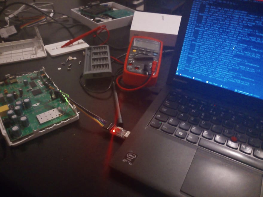
With a multimeter, it was easy to find out the GND pin with a connectivity test, and the VCC with a volt check, which showed that the board ran at 3.3V. However, finding the right RX / TX required some extra work. Connecting a cheap logic analyzer to the GND/RX/TX pins, and using the Saleae Logic 2 Alpha software, allowed to find the right combination. You may have to adjust the capture frequency in the Saleae software for the device’s proper functioning.
The only missing thing was to find the right baud rate to connect to the UART port, which can be achieved by checking the transmission time of one bit, calculate the inverse and multiply by 1 000 000. The transmission time is approximately 8.688uS: (1/8.688)*1000000 = 115101, which is close to the common baudrate of 115200.
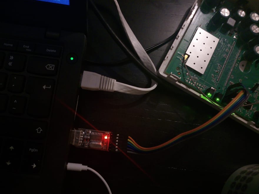
Connecting the USB to UART (FT232 USB UART) to the exposed pins (do not forget, RX of the router to TX of the FT and TX of the router to the FT RX), connecting to the device using screen, and connecting the device to power, and we have a UBoot loading!
$ screen /dev/ttyUSB1 115200
`
ROM VER: 1.0.3
CFG 01
Read
ROM VER: 1.0.3
CFG 01
Read EEPROM
X
1.0.2 (Dec 1 2008 - 13:39:09)
DRAM: 32 MB
relocate_code start
relocate code finish.
Manf ID:0000007f
Vendor ID:000000cb
Flash: 8 MB
In: serial
Out: serial
Err: serial
Net: ethaddr=00:22:B0:F0:15:9B
DO GPIO2 PULL HIGH OK for USB POWER ON
danube SwitchDO GPIO30 SW_RESET OK
Type "run flash_flash" to start Linux kernel
Hit any key to stop autoboot: 3 ... 2 ... 1 ... 0
Booting image at b0080000 ...
Image Name: MIPS Linux-2.4.31
Created: 2009-10-01 9:55:04 UTC
Image Type: MIPS Linux Kernel Image (lzma compressed)
Data Size: 4902944 Bytes = 4.7 MB
Load Address: 80002000
Entry Point: 801ec040
Verifying Checksum ... OK
Uncompressing Kernel Image ... OK
Starting kernel ...
Reserving memory for CP1 @0xa1f00000
memsize=32l
flash_start=0xb0000000
flash_size=8388608l
`
We have some new information as a result of this capture:
- 32 MB of DRAM (which checks with the NANYA NT5DS16M16CS-6K chip description)
- 8 MB of flash (which also matches the EN29LV640B-90TIP specification)
- The processor is MIPS and runs Linux (
Image Name: MIPS Linux-2.4.31) - The image is
lzma compressed, relevant man page. - The flash size is
8388608land starts at address0xb0000000.
By interrupting the boot by pressing any key (Hit any key to stop autoboot: 3 ... 2 ... 1 ... 0) we enter U-boot. The U-boot is the device bootloader, understands the device’s memory map, starts the main firmware execution and carries other low-level tasks. For more about the common commands and features RTFM.
Two main tasks can be done using the U-boot CLI for reverse engineering purposes: (1) understanding the memory map and, potentially, exfil the firmware and (2) bypass the authentication protection of the Linux image with the init=/bin/sh trick. @cybergibbons has two very good videos on that: Rooting via Uboot and Firmware Recovery.
Although neither of those tasks was carried we can see some interesting U-boot applets present (only a few selected ones are shown):
`
DANUBE # help
bdinfo - print Board Infostructure
ping - Send ICMP ECHO_REQUEST to network host
printenv- print environment variables
setenv - set environment variables
tftpboot- boot image via network using TFTP protocol
`
And some extra information can be collected using bdinfo:
`
DANUBE # bdinfo
boot_params = 0x81F7BFB0
memstart = 0x80000000
memsize = 0x02000000
flashstart = 0xB0000000
flashsize = 0x00800000
flashoffset = 0x00000000
ethaddr = 00:22:B0:F0:15:9B
ip_addr = 5.26.62.222
baudrate = 115200 bps
`
And also from the environment variables using printenv (only a few selected entries are shown):
`
DANUBE # printenv
bootcmd=run flash_flash
f_firmware_size=0x00027000
f_firmware_addr=0xb0040000
ipaddr=5.26.62.222
serverip=5.26.62.23
`
We could carry tasks such as boot a firmware over TFTP or change the bootcmd to anything we needed. However, as it will be shown, this was not required since the device has default credentials to root.
I’m Root
Letting the device boot completely while connected over UART we can click any key for the Login prompt to appear. Using the default credentials of most DLink routers, admin / admin, we can log in as root.
`
BusyBox v1.00 (2009.10.01-09:47+0000) Built-in shell (msh)
Enter 'help' for a list of built-in commands.
`
BusyBox provides a set of Linux applets to interact with embedded Linux devices. Dumping some info using the available applets (shortened):
`
DVA-G3170i/PT # uname -a
Linux (none) 2.4.31-Danube-3.3.0-G0432V33_BSP #1 Sat Jan 10 09:47:00 CET 2009 mips
DVA-G3170i/PT # cat /proc/cpuinfo
system type : DANUBE
processor : 0
CPU model : unknown V4.1
BogoMIPS : 222.00
DVA-G3170i/PT # cat /proc/meminfo
total: used: free: shared: buffers: cached:
Mem: 27942912 26931200 1011712 0 2961408 8605696
DVA-G3170i/PT # ls
www tmp proc htdocs etc
var sbin mnt home dev
usr root lib firmware bin
`
Exfil Files
One strategy used was to log all the interactions using screen to a file and then recover the files manually:$ screen -L /dev/ttyUSB0 -L creates a screenlog.0 automatically with a record of all interaction.
Another strategy would be to extract the firmware from the SPI flash chip with a similar process as the one carried in a previous blog post.
The available telnet service was used for quickest access: $ telnet 192.168.10.1 with the same credentials as the Web Admin GUI: admin / admin.
With this, and using one of the applets available in the BusyBox, the tftp client, it was possible to retrieve/send files from/to a remote host. This allows to quickly transfer files from the device, easing the process of inspecting them. For creating an instant and temporary TFTP server, the py3tftp was used (after trying several other options without success). As an example, to extract the firmware.bin which can be found in the /firmware folder one can do:
- In the local machine:
$ py3tftp --host 0.0.0.0 -p 2121 -v - In the router:
DVA-G3170i/PT # tftp -p -l /firmware/firmware.bin 192.168.10.x 2121
What happens at boot?
To better understand what happens when the device boots more cleanly, a factory reset was made by clicking the RESET button. The HOUSEKEEPER process detects that the button is pressed for 5 seconds and then reboots the device.
`
00:06:08 HOUSEKEEPER: factory reset button pressed for 1 secs
...
00:06:12 HOUSEKEEPER: factory reset button pressed for 5 secs
00:06:14 HOUSEKEEPER: trigger FACTORY RESET...
`
Most of the called scripts are either stopping or resetting services. After that, some extra scripts are called to do what seems to be the device’s bootstrapping. After that, the device reboots itself and does a standard boot procedure (as shown before).
`
[/usr/sbin/submit] FRESET ...
[/etc/scripts/misc/freset.sh] ...
[/etc/templates/wan.sh] [stop] [] ...
[/etc/templates/igmpproxy.sh] stop ...
[/etc/scripts/misc/profile.sh] reset ...
[/etc/scripts/misc/profile_action.sh] reset ...
[/etc/scripts/misc/defnodes.sh] ...
[/etc/defnodes/S10syncnodes.sh] ...
[/etc/defnodes/S11setext.sh] ...
PHP [/etc/defnodes/S12setnodes.php] ...
[/etc/defnodes/S13setext.sh] ...
PHP [/etc/defnodes/S14setnodes.php] ...
PHP [/etc/defnodes/S16features.php] ...
PHP [/etc/defnodes/S20setnodes.php] ...
PHP [/etc/defnodes/S40brand.php] ...
PHP [/etc/defnodes/S50showdect.php] ...
[/etc/scripts/misc/defnodes.sh] Done !!
[/etc/scripts/misc/profile.sh] put ...
[/etc/scripts/misc/profile_action.sh] put ...
[/etc/scripts/misc/freset.sh] reset config done !
The system is going down NOW !!
`
The scripts are located in the /etc folder in different folders, with some being sh's and others PHP’s. This is useful since now we known where to look to understand specific parts of the behaviour of the router, including how it generates the WiFi passkey or how it sets the transmit power of the WiFi (which implies that it stores information about the country of operation).
Wireless and WPA Key Generation
Since this is a pretty old router, the WPA key generation algorithm is well-known and part of the Router Keygen application. Implementation is open-source and available here. First off, the WiFi SSID and passkey should be stored somewhere in the device. After some search in the boot log file, the following lines caught my attention:
`
Start ALL WLAN ...
[/etc/templates/wlan.sh] start 1 ...
[/var/run/wlan_if_start1.sh] ...
Start setup WLAN interface ath0 ...
`
Looking into the /etc/templates/wlan.sh script we can observe several curious things:
TEMPLATES="/etc/templates/wifi"

WLAN=
OPERATE_MODE=
...
case "$1" in
1|start|restart)
...
    if ["$OPERATE_MODE" = "0" -o "$OPERATE_MODE" = ""]; then
            rgdb -A $TEMPLATES/wlan_if_run.php -V generate_start=1 -V wlanid=$2 > /var/run/wlan_if_start$2.sh
            rgdb -A $TEMPLATES/wlan_if_run.php -V generate_start=0 -V wlanid=$2 > /var/run/wlan_if_stop$2.sh
...
`
First, there is a utility called rgdb that allows one to retrieve configuration values, e.g. the OPERATE_MODE. rgdb is an alias for the rgbin binary, and from here:” /usr/sbin/bin appears to be the userspace utility for reading and writing the “NVRAM” area of flash. In the NVRAM area is that gzip’ed XML MIB file which contains the configuration parameters to disable LAN access and lock the device.”
hostapd file
Looking into the PHP script wlan_if_run.php which is located in the folder /etc/templates/WiFi, we can see that it checks for any changes in the system configuration (I supposed that these changes correspond to the ones made using the Web Admin GUI) and updates the system files accordingly, including the hostapd config file: $hostapd_conf = "/var/run/hostapd".$wlanid.".conf";. Looking for the config file in the /var/run/ we can find it:
`
/var/run/hostapd1.conf
interface=ath0
bridge=br0
ssid=DLink-F0159B
wpa=1
driver=madwifi
ieee8021x=0
eapol_key_index_workaround=0
logger_syslog=0
logger_syslog_level=0
logger_stdout=0
logger_stdout_level=0
debug=0
wpa_group_rekey=3600
wpa_pairwise=TKIP
wpa_key_mgmt=WPA-PSK
wpa_passphrase=8XYXNqrqX85XX5rN8q8Y
`
Here we can see the SSID of the network, in this case, DLink-F0159B and the generated password (remember that we did a RESET): 8XYXNqrqX85XX5rN8q8Y.
- The generation of SSID was evident: the MAC address of the device is
00:22:B0:F0:15:9Band the SSID isDLink-plus the last 3 pairs of hex digits without the separator:F0159B. - The generation of the password was a little more fun to discover. While this could be configured manually in the device’s firmware, this would imply extra costs for the manufacturer (each device would have to persist a unique token); thus, it is not common. More common is that the script that generates the passwords is stored on the device and when the device is booted for the first time (or RESETed) it uses some
logicto define a unique password. This password can either be always the same for a specific device or not depending on the seed used, but, once again, the first is more common.
Further looking into the boot logs and the WLAN related scripts something pop-out with the word keygen in it (file /etc/defnodes/S13setext.sh):
`
!/bin/sh
echo [$0] ... > /dev/console
LANMAC=rgdb -i -g /runtime/layout/lanmac
WLANMAC=rgdb -i -g /runtime/layout/wlanmac
DSL_WANIF_MAX=rgdb -i -g /runtime/layout/dsl_wanif_max
WLANIF_MAX=rgdb -i -g /runtime/layout/wlanif_max
bootcodeversion=rgdb -i -g /runtime/sys/info/bootcodeversion
ADSL WANMAC
i=1
while ["$i" -ge 1 -a "$i" -le "$DSL_WANIF_MAX"]; do
xmldbc -x /runtime/wanmac/wanmac$i "get:alpha_macaddr $LANMAC 0 $i"
i=expr $i + 1
done
WLAN MAC
i=1
j=0
while ["$i" -ge 0 -a "$i" -le "$WLANIF_MAX"]; do
xmldbc -x /runtime/wlanmac/wlanmac$i "get:alpha_macaddr $WLANMAC 1 $j"
i=expr $i + 1
j=expr $j + 1
done
bootcodeversion
bootcodeversion=echo $bootcodeversion | tr -d \"
rgdb -i -s /runtime/sys/info/bootcodeversion "$bootcodeversion"
wpa-psk keygen
xmldbc -x /runtime/wpakey "get:wpakeygen $LANMAC"
`
A new curious binary appears, the xmldbc, which is located in /usr/sbin/xmldbc. From here: “the xmldbc tool has all the commands needed to set the elements (nodes) in the XML MIB”, MIB standing for management information base, which is a database used for managing the entities in a communication network. It can also run commands and set variables in the MIB with the result. So this appears to be where the wpa-psk is generated and, then, stored. The command executed is wpakeygen $LANMAC where the $LANMAC is equal to the $WLANMAC one.
Reversing the wpakeygen
Looking for the wpakeygen binary, we can find it in the same folder: /usr/sbin/wpakeygen. Transfering the binary to my machine using the configured TFTP allows one to debug it and understand what it does to generate the key. Firing up Ghidra with it we can confirm that it is indeed a MIPS binary:
`
ELF 32-bit MSB executable
MIPS
MIPS32 version 1 (SYSV)
dynamically linked
interpreter /lib/ld-uClibc.so.0
stripped
`
Looking for the main function in the function tree we can find the wpakeygen_main which seems a rather good candidate, so lets look at the p-code:
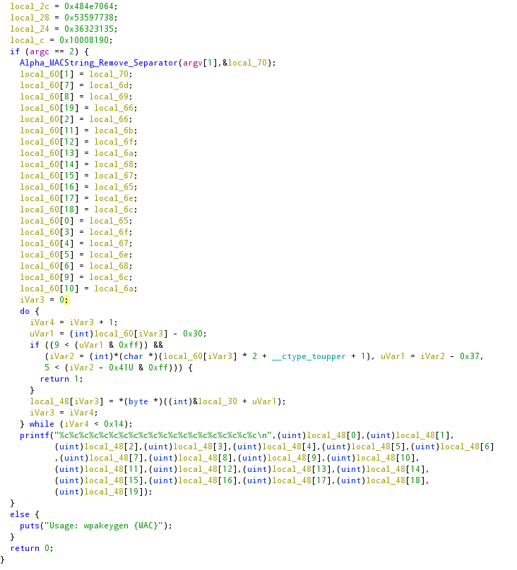
The first part of the code, which is not shown, defines the variables and reads the MAC as the argument. Then the function Alpha_MACString_Remove_Separator is called, and, by its name, we can conclude that it removes the MAC address separator between the pairs of hex digits. In the following lines, this function’s return is stored (including repetitions), in a mostly-random way, in a string with 20 chars of size.
Lastly, an iteration over those 20 chars is carried, and in the last lines of the loop, a resulting index value is used to get something (a char) from a memory position. Searching for that position in the memory, we find the scalar XrqaHNpdSYw86215U. So the password is made of chars taken from random positions of that scalar string (of 17 chars), giving a final password of 20 chars, which meaning that bruteforcing would result in 17^20 possibilities, which equals: 4 064 231 406 647 572 522 401 601. So, bruteforcing would take some time…
So, let us reverse the remaining p-code:
-
uVar1 = (int)local_60[i] - 0x30;: Takes the char at posiand subtracts0x30; - The following
ifdoes a lot of things, breaking it into parts by the&&:-
(9 < (uVar1 & 0xff)verifies thatuVar1 & 0xffis greater than9; -
(iVar2 = (int)*(char *)(local_60[i] * 2 + __ctype_toupper + 1), uVar1 = iVar2 - 0x37, 5 < ())also does lots of stuff using thecomma operator. In a condition, the comma operator runs all the instructions but only evaluates the value of the rightmost one, which isiVar2 - 0x41U & 0xff > 5. The remaning ones: -
iVar2 = (int)*(char *)(local_60[i] * 2 + __ctype_toupper + 1)converts thelocal_60[i]to uppercase; -
uVar1 = iVar2 - 0x37just updates the value ofuVar1by subtracting0x37toiVar2.
-
At last, the resulting wpa-psk is printed with printf.
Converting all of this logic to Python gives something similar to the following:
`
1
2
3
4
5
6
7
8
9
10
11
12
13
14
15
16
17
18
19
20
21
22
23
24
25
26
27
28
29
30
31
32
33
34
35
36
37
38
39
40
41
42
43
44
45
46
47
magic_key = "XrqaHNpdSYw86215U"
mac = list("0022B0F0159B".replace(':', ''))
str1 = [""]*20
str1[1] = mac[0]
str1[7] = mac[3]
str1[8] = mac[7];
str1[19] = mac[10];
str1[2] = mac[10];
str1[11] = mac[5];
str1[12] = mac[1];
str1[13] = mac[6];
str1[14] = mac[8];
str1[15] = mac[9];
str1[16] = mac[11];
str1[17] = mac[2];
str1[18] = mac[4];
str1[0] = mac[11];
str1[3] = mac[1];
str1[4] = mac[9];
str1[5] = mac[2];
str1[6] = mac[8];
str1[9] = mac[4];
str1[10] = mac[6];
i=0
result=[""]*20
index = ""
tempvar1 = 0
tempvar2 = 0
while(True):
t = ord(str1[i]);
tempvar1 = t - 0x30

if (tempvar1 & 0xff) > 9:
    tempvar2 = ord(str1[i].upper())
    tempvar1 = tempvar2 - 0x37
    if (tempvar2 - 0x41 & 0xff) > 5:
        print("error")
        break

result[i] = magic_key[tempvar1]
i=i+1
if i >= 20:
    print("".join(result))
    break
`
Exploring the xmldbc and rgbd binaries
Both the xmldbc and rgbd are used to interact with stored values in the system. These binaries have been used in the DLink routers for years, and one funny trick with xmldbc is that the binary can be used to dump all the persistent configurations of the router:
`
DVA-G3170i/PT # xmldbc -d /tmp/dump.xml
DVA-G3170i/PT # cat /tmp/dump.xml
;remaining 2659 lines
DVA-G3170i/PT # tftp -p -l /tmp/dump.xml 192.168.x.x 2121
`
And we now have all the router configs which include:
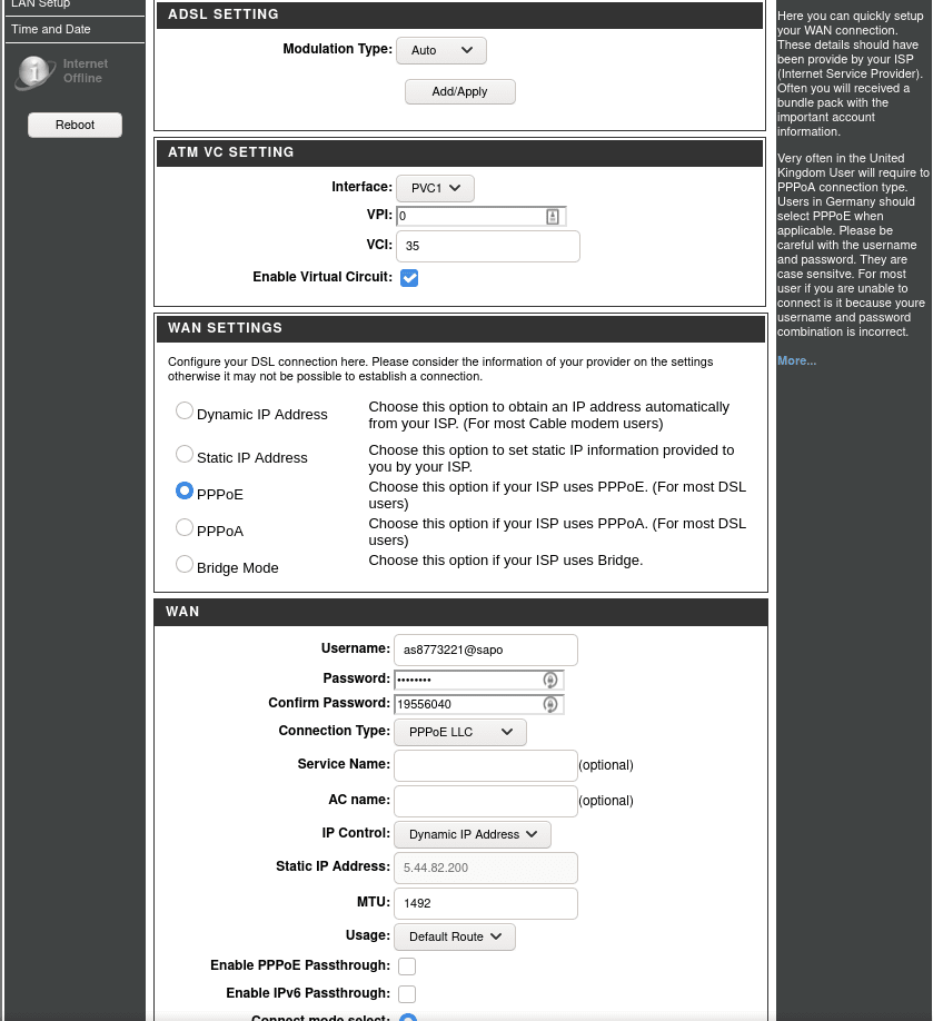
- the username and password of the DSL line if configured (defaults shown):
`
as0000000@sapo
master_ph!
`
- all of the valid user credentials for accessing the router (defaults shown):
`
admin
admin
0
user
user
1
`
- the crendentials and endpoint of the ISP-configured TR-0691 ACS server (Auto Configuration Server (ACS) enables Telcos and ISPs to manage their devices remotely):
`
██████████████
██████████████
http://███████████.███.sapo.pt:█████/cwmpWeb/CPEMgt
`
We can now use the same utility to change some configuration values, e.g.:
- Remove the PPPoE ISP block:
xmldbc -i -s /runtime/web/pppoelock 0 - Remove the VoIP lock:
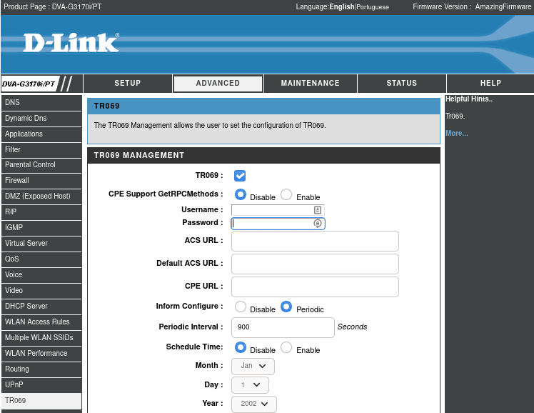
xmldbc -i -s /runtime/web/voiplock 0 - Show the TR-069 menu on the Web Admin GUI:
xmldbc -i -s /runtime/web/tr069hide 0 - Change the Firmware Description:
xmldbc -i -s /runtime/sys/info/firmwareVersion AmazingFirmware
All of this modifications can also be carried using the Web Admin GUI, e.g.: 192.168.10.1/auth.xgi?set/runtime/web/tr069hide=0.
Wrap Up
While this is by now a mostly-unused router, an advanced search using the WiGLE shows that 138 unique APs are broadcasting an SSID with a similar format (DLink- ______ ) and that share the same first three pairs of hex digits of the MAC address (manufacturer code), 00:22:B0, in Portugal last seen of Jan of 2019. Given the history of people not changing default passwords, this can still be a problem today.
Query (must have an account on WiGLE): https://wigle.net/search?lastupdt=20190101000000&netid=00%3A22%3AB0&ssidlike=DLink-______&country=PT#fullSearch
Another fun binary to do reverse would be the led_gpio_ctl which seems to be controlling the status LEDs. Maybe adventures for another time.
This post would not be possible without the help and contributions of @Pedro_SEC_R, @0xz3z4d45 and @mluis. Kudos!
TR-069 “is a technical specification of the Broadband Forum that defines an application layer protocol for remote management of customer-premises equipment (CPE) connected to an Internet Protocol (IP) network.” ↩





Top comments (0)
Some comments may only be visible to logged-in visitors. Sign in to view all comments.